
Download .pdf file : Click!
----------------------------------------------------------------
ENHANCEMENT OF AVAILABILITY OF 4D SIMULATION
BASED ON BUILDING INFORMATION MODEL TECHNOLOGY
Jong Jin Park1, Eon Yong Kim2, Hyun Cho3, and Han Jong Jun4
¹ Ph.D. Candidate, Department of Architecture, Hanyang University, Seoul, Korea
² Ph.D. Candidate, Department of Architecture, Hanyang University, Seoul, Korea
3 Graduate Student, Department of Architecture, Hanyang University, Seoul, Korea
4 Associate Professor, Department of Architecture, Hanyang University, Seoul, Korea
Correspond to ikaros7979@gmail.com
ABSTRACT: 4D simulation integrates the 3 dimensional model of a building with the construction schedule, and it leads to the possibility of virtually checking the construction process and the building itself in advance. However, the existing problem of 4D simulation is the difference between the demands of architects, engineers, and construction site workers in 4D simulation. This study suggests the possible way to enhance the availability of 4D simulation, considering more the practical demands from the construction site. In order to conduct this study, we build a 3D BIM model of a business-residential complex and link the model with the pre-defined construction schedule in order to make a 4D simulation. This study concludes with the optimized 4D simulation methodology based on BIM model considering the demands in perspective of the construction site. It would contribute to the harmonic collaboration among architects, engineers, and labors in the construction site when using 4D simulation based on BIM model.
Keywords: BIM (Building Information Model), 4D Simulation, Visualization
1. INTRODUCTION
Current planning processes in the construction industry are still mainly based on 2D drawings and printed construction schedule. However, since construction projects become more massive and complex, 2D drawings and information are not appropriate enough for architects and constructors to manage and control the projects. Moreover, most of construction projects are based on orders, within a limited time at a specific location. These factors lead to the low productivity, low efficiency and the heavily dependency on the experience of the traditional construction system, instead of a systematic and developmental method.
Against this backdrop, various laboratories and companies are constantly researching on applying state-of-the-art IT technology to the construction projects by setting up the construction integrated management system. Through assiduous researches, architectural integrated information management system based on BIM technology rises into prominence in the Architecture, Engineering, Construction and Operations (AECO) industry.
BIM technology supports architects, engineers, and constructors to enhance the efficiency and accuracy of project plans, and can be applied to construct 4D simulation by adding concept of time so that it is easy to understand the process of construction visually.
Various visual representations of a project's schedule and associated information (e.g. congestion plots) combined with visual representations of the project in progress (i.e. 4D CAD) can assist greatly with the tasks of identifying effective construction strategies for shortening project duration, assessing their workability, and judging overall schedule quality. They aid communication amongst project staff and facilitate brain-storming, and, implemented well they can provide clear, fast, and multi-dimensional feedback to the project team [1].
Described in this paper are selected aspects of our project and related findings at formulating a systematic visualization environment that links 3D BIM model in order to assist with the requirement to formulate and evaluate construction to meet project duration requirements, and to facilitate the communication among designers, engineers, construction site officials and workers. In particular, we are interested in exploring product and process modeling (representation) issues in terms of 4D simulation work-flow, levels of detail, and communication among construction-related officials to create 4D simulation model based on BIM technology needed to apply it successfully in the construction site.
Use is made of a business-residential complex project that is of sufficient scale (3 buildings of 80 stories and a business facility of 9 stories) to highlight aspects of our approach and identify important issues that must be addressed if a company newly introduces a 4D visualization environment into their construction project.
2. BACKGROUND OF 4D SIMULATION
2.1 Brief Overview of BIM (Building Information Model)
BIM (Building Information Model) has been the one of the main keywords in recent researches that try to introduce the latest IT technology into the architectural process. BIM can be defined as a paradigm or a process that collect all the data of a building extracted from all the phases of the life-cycle, and that modify, reuse, and optimize the data in order to eventually increase the quality of design and building performance.
Development of three-dimensional computer-aided design technologies have furnished the opportunity for enterprises to advance the management of construction projects via sharing building information visually. With the support of this 3D model, architects, engineers, constructors, and other related officials can virtually construct, extend the analysis, explore the possibilities, calculate construction costs, study what-if scenarios, detect possible clashes, analyze constructability, and manage and maintain a building.
Building Information Models are consisted of 'smart' objects [2] which represent physical elements of a building like windows, doors and columns, and encapsulate 'intelligence' [3]. Fig. 1 shows a flow diagram of Building Information Models and their objects. [4]
After completing 3D BIM model, project designers and contractors use this model combined with the project schedule in creating 4D simulation.
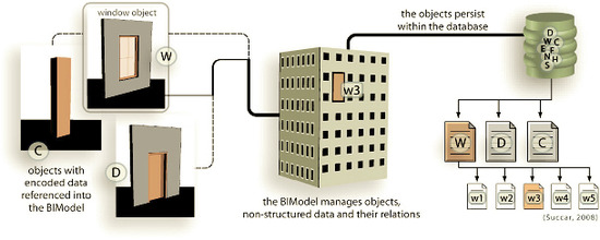
Fig. 1. Building Information Models and their objects - flow diagram
2.2 4D Visualization and Simulation
4D simulation of construction sequences is an adequate tool for visualizing inherently abstract and complex time scheduling data which are otherwise buried in deeply nested Gantt charts. Today's available 4D simulation software is in principle capable to generate visualizations which intuitively illustrate construction processes along the timeline. By linking the objects of a three dimensional model to the tasks in a time schedule, it helps to reduce major scheduling errors just by inspection and improves communication within the project team. [5]
2.3 Process of 4D Simulation
As explained earlier, a construction plan specifies tasks to erect a building, the time of these tasks and the relationships of these tasks about how they are flowed. In order to create a 4D simulation, a three dimensional BIM model is required, followed by the time consuming task to link 3D objects of a building to the construction schedule manually or semi-automatically.
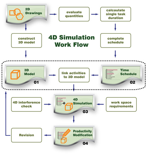
Fig. 2. 4D Simulation Work Flow
3. Case Study : Fulton Street Transit Center Project(FSTC Project) [6]
This section introduces a case study of a project that applied 3D and 4D model system to visually support the necessary engineering decision making. This project was mainly benchmarked and referred for our project that will be discussed in the Section 4.The Fulton Street Transit Center is one of the major subway reconstruction project in New York City which refurbishes the seven subway lines around the Fulton street. Furthermore, the Transit Authority plans to build a new above ground Transit Terminal. With the support of 4D simulation, the construction management team was able to simulate these construction sequences and schedules and visually evaluate the planned construction.
Table 1. [6] shows a chart displaying the projects challenges and the various applications of the 3D/4D model. FSTC project team manages 3D/4D model to engage these challenges on the project.
3.1 Strategies of 4D Simulation
Due to the tight site conditions in lower Manhattan, it is important to impact car and subway traffic as little as possible. Additionally, construction managers need to coordinate the various different contractors and sub-contractors that will work concurrently on the tight site. The TA hires a consultant construction management (CCM) team that is mainly responsible for constructability review of the design and overall construction packaging strategy.
The CCM team developed guidelines and standards while implementing the 3D/4D process in order to cope with the challenges in the Table 1. The CCM team has integrated the 3D/4D modeling team into its organizational hierarchy: Project Director, Project Managers , Scheduling Team, 3D/4D Modeling Managers, 3D Modeling Team.
Table 1. Project Challenges and Application of 3D/4D model in FSTC Project
Project Challenges | ||||||||
Complex Design | GO Schedule | Passenger Flow | Road Traffic | Public Concerns | Tight Site Conditions | Multiple Contractors | ||
Application Of 3D/4D Model | Understanding Design | O | ||||||
Constructability Review | O | O | O | O | O | O | ||
Construction Sequencing | O | O | O | O | O | |||
Support of Master Schedule Review | O | O | ||||||
Support of Contractor Review | O | O | ||||||
Team Communication | O | O | O | O | O | O | ||
Visualization Support for Client and Public | O | O | O | O | O | |||
3.2 3D/4D Model Application
In order to meet the project challenges, the CCM team has applied the 3D/4D models for the following evaluation tasks: Design Understanding, Constructability Review, Construction Sequencing, Master Schedule Review, Contractor's Schedule Review, Team Communication, and Visualization Support for Clients and Public.
As the subway line cannot be closed down during weekdays, the CCM has to integrate its schedule into the prescribed weekend GO schedule. Furthermore, the construction team has to maintain the passenger flow and safety at all times. Therefore, the CCM team used the 3D/4D model for this part of the project supporting understanding the design and reviewing the contractor's schedules.
After analyzing this project, this report suggests 3D/4D implementation guidelines based on the experience and the research of this project (Table 2). Based on this guidelines we try to apply the 4D simulation on our project.
Table 2. Guidelines for 4D simulation suggested by FSTC Project
Main Issue | Sub-Issues | Requirement for a successful 4D Simulation |
Data Acquisition | 2D Design Data | -Necessary to have the original electronic CAD file and to a CAD data exchange process. -Effective communications between 3D/4D modeling team and the design team in order to avoid costly rework for the design revision. - A local or extranet-based storage all project members can access to. - Structure, naming, layer standard for CAD files. |
3D Design Data | - Appropriate level of details according to the purpose and the user of the 3D model - Compatibility of the file format. | |
Schedule Data | -Accessibility to the latest versions of the schedule in the main database. - Establishment of read-only access to the database for 4D team. | |
3D Modeling | Handling Information Sources | -Implementation of a system that stores and tracks the file revisions. |
3D Model File | -Different files for various disciplines like architectural, structural, and electrical design. -Use of one mutual file format that all applications can import. -Establishment of a file naming convention using codes. | |
3D Object Hierarchy | -A separate 3D object for each schedule activity that is to be represented within 4D model -A preliminary convention for splitting up 3D objects for 4D simulation. -Grouping the objects in each of the 3D model files according to various types of building components. -Use of coloring scheme for 3D building components. | |
Unique IDs Of 3D objects | -Use of the unique ID of the 3D objects that is assigned in the 3D modeling applications for the purpose of the automatic re-linking update. | |
Linking 3D model with schedules | Preparation for 4D modeling | -Decision making which activities are linkable to geometry, and which are not according to 4 different kinds of activity types: Construction, Demolition, Temporary, and Renovation activities. -Creation of 4D groups reflecting the hierarchy of the schedule |
4D modeling | -Verification whether inconsistencies are caused by a non-logical schedule or by an error made during the linking process. -Consistency of object IDs with schedule activity IDs in order not to lose established links. |
4. APPLYING 4D SIMULATION
We conduct a pilot project in order to figure the appropriate procedure of 4D simulation in a business-residential complex building. Throughout this project, we try to illustrate: (a) how 3D model should be created for 4D simulation, (b) the benefits of 4D simulation in the construction site, (c) what the demands for construction officials are for 4D simulation, (d) how the 4D simulation procedure should be in large scale of the project, and (e) the possibility of 4D simulation in applying to various project types. We work with a contractor and an architectural firm with the support of 4D modeling application professionals.
4.1 Background on projectThe pilot project is a business-residential complex with 3 buildings of 80-story high and a commercial building of 9-story high that D construction company is in charge for the construction. The construction company suggests to create 4D simulation for one of the 4 buildings, a 80-story residential building. The building is situated in Pusan, Korea with construction to be completed by no later than January 2012.
4.2 Scope of the project
The scope of the 3D/4D simulation of this project embraces: (1) 3D BIM modeling, (2) 4D simulation, and (3) Visualization with animation. Unfortunately, we did not get involved in it from the design phase of this project. When we start this project, all the designs and 2D drawings are already completed.
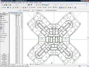
For the 3D BIM modeling task, we do not create every detail of the building from the basement to the top floor, but we do a core, slabs, curtain walls, sky decks, ACS, RCS, aluminum form, gang form, steels, concrete, and link beam, etc. for 4D simulation (Fig. 3). The 4D simulation part includes core, peripheral elements, and curtain walls from 5~20F, ACS/RCS from 15~20F, process of implementation of sky decks in 16F, etc. For the last task, we create visual animation of overall bird's eye view of the completed complex, and the construction process of one room type including all the structural and architectural components and facility equipments.
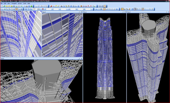
Fig. 3. Target building for 4D simulation of the project, created by 3D BIM tool
4.3 Process of 4D simulation
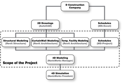
As mentioned in section 4.1, our part of this project starts after the site construction initiated. We get all the 2Ddrawings (*.dwg file format) needed for 3D BIM modeling and the construction schedule created from MS-Excel (*.xls file format).
With CAD file, we create 3D model in 3 different parts with 2 different 3D modeling applications : structure modeling (Revit Structure), curtain walls (Revit Architecture), and temporary facilities in the construction site (Revit Structure). Furthermore, with the construction schedule we re-build it with MS-Project because of the file compatibility of our simulation tool (NavisWorks Manager). All 3D objects are linked to respective activities, created from MS-Project, with NavisWorks Manager and simulated with NavisWorks Freedom. Fig. 4. represents overall process of our project in terms of 4D simulation.
4.4 3D modeling
As indicated previously, 3D modeling process needs to be related to the construction schedule, and to be created concerning 4D simulation. However, when we got involved in the project, the construction schedule was not complete due to the Fast-Track method although the site construction had been initiated. Therefore, we were only able to follow the incomplete schedule and the modeling procedure based on the characteristics of the 4D modeling tool, which was NavisWorks.
Through the meeting with some of construction officials, we come out with 3 important factors for 3d modeling.
1) Core should be modeled split down into 2 groups since it is constructed with different time schedules.
2) Slabs should be divided into 4 different zones. The building has 4 wings and according to these 4 zones, construction schedule is set up.
3) Only main steel beams are required to be modeled, and detailed steel beams do not need to be created in 3D model because beams are set up dependent on the labors' experience on the construction site.
According to these rules, we created structural and architectural (curtain wall) model with Revit Architecture and Revit Structure (Fig. 5).
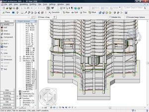
When creating 3D architectural component, we follow the naming code rule concerning the construction sequence (e.g. 1-Peripheral Slab, 2-Peripheral Slab, etc.). In addition, when we create curtain walls we have to create around 320 single component units for one floor due to the fact that each curtain wall unit needs to be simulated separately in the 4D simulation.
4.5 4D modeling
For 4D modeling, we have to convert the given Excel (*.xls) file of the schedule into the MS-Project file (*.mpp) since our 4D simulator, NavisWorks, can import MS-Project file rather than Excel file format.
3D BIM objects are linked construction activities in NavisWorks in 2 different ways: Search Set (automatic) and Selection Set (manual). Search set automatically links 3D objects to the activities by search option. We set a search option according to the names of objects and activities, then the grouped components are linked and updates automatically by the search set function. Other components that cannot be connected by search set are linked by selection set which is a manual linking system. These components are mainly beams, because when we import 3d beam objects, their properties of level information are lost, so we link them manually.
4.6 4D simulation
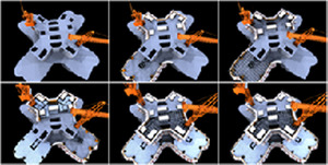
After completing 4D model, we make a 4D simulation based on the schedule of 3-day-method, and make a presentation of its animation at the meeting with construction officials. Fig. 7. shows snapshots of 3-day-method.
5. DISCUSSION
When we have our first meeting with the construction officials, we show the semi-completed 3-day-method animation created by NavisWorks. After seeing the animation, most of the meeting participants are satisfied with the outcome and the potential of the 4D simulation, and are in sympathy with the necessity of the further research and more pilot projects.
On the other hand, construction officials point out some aspects that need to be modified and revised that we do not expect. At the first stage of the project, we were asked to make a 4D simulation of the 3-day-method only, but after the simulating meeting, the expectations from the construction site get bigger and bigger so that it is demanded to create another simulation for curtain walls, temporary facilities, concrete pouring plan.
The following table (Table 3) shows the specific revisions or problems pointed out from the construction site and their solutions.
Table 3. Required modification of 3D/4D models
3D Modeling part | |
Problem | -No specifications of temporary facilities including ACS, RCS and tower-cranes have not been decided due to Fast Track method. -As construction schedule becomes detailed, the previous 3D objects need to be recreated . |
Solution | -Request the construction site and related companies for the facilities specification and information in order to create their 3D model. -Slabs and curtain walls are rebuilt or modified according to the new schedule. |
Construction schedule part | |
Problem | -Since temporary facilities are set up after working hours, they are not represented specifically in the schedule. |
Solution | -We add new naming codes for all the temporary facility setting up activities in MS-Project schedule. |
4D simulation part | |
Problem | -Some of new 3D objects are needed to link with the new schedule manually. -When construction officials see the first simulation, some of them questioned about the construction sequences. -Different officials in the different position want to respective level of details for 3D objects and 4D simulation. |
Solution | -Due to the limits of the 4D modeling application, they are linked manually. -By a meeting with every construction officials, we reorganize and replan the hierarchy of 3D modeling strategy. |
Visualization part | |
Problem | -We are asked to create more 3D objects such as landscape, surrounding buildings and room type sample for the visualizations. |
Solution | -We spend more time to create 3D objects with another 3D modeling application for visualization. |
As you can see in the above chart, there are three main concerns when creating 3D/4D models.
1) Although the project goes on Fast-track method, it is important to make a construction schedule as detailed as possible in the early stage.
2) When creating 3D objects, 3D modelers are required to split down them into appropriate units according to the construction activities.
3) Since different level of details are asked from the construction site, it is suggested to make an agreement of the visual details in advance.
More than anything else, the most important aspect for the successful 4D simulation is the communication among all the related members. Recently, more and more construction project introduces fast-track method for their construction strategies, and it is desirable for all the members to get together and communicate smoothly with all the opinions open. The major aspects and strategies for 3D/4D modeling task can be decided at this point so that it can reduce the construction budget and duration.
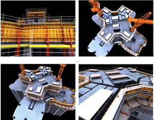
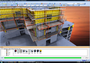
Fig. 8. The final 4D simulation of this project
6. CONCLUSIONS
4D construction planning provides the ability to represent construction plans graphically [7] by adding the temporal dimension to 3D CAD models, i.e. linking a 3D graphical model to a construction schedule through a third party application [8]. 4D visualization tools can demonstrate the entire construction progress in a vivid way and show potential conflicts in a construction site. Planners can also practice what-if analysis to assess and compare several planning options in order to select a better strategy [9].
In this study, we create a 3D/4D BIM model of a business-residential complex in Pusan, Seoul, Korea in order to introduce 4D simulation effectively in the construction site. Through several meetings and problem solving processes, we conclude three main factors for successful 4D simulation: (1) Pre-defined construction schedule as detailed as possible, (2) 3D modeling strategy according to the construction activities and (3) An appropriate level of details concerning the final users of 4D simulation.
Although we get involved in this project after the site construction has initiated, we can come up with the similar important factors for 4D simulation as mentioned in the guidelines from FSTC project. In addition, it is suggested to establish a company, which might be called Virtual Construction Manager, whose role is to control and manage the smooth communication among 3D and 4D modelers and the construction site officials for the effective and successful 4D simulation.
It is very impressed, when we have the meeting in the construction site, that they want to use the 4D simulation displayed in a big screen in the construction site so that all the labors can understand easily the construction process from the visual details and can carry out their tasks accurately according to it. Also, it can take a role as another communication means with foreign labors. The efficiency and necessity of 4D simulation is very highly praised from the construction site as a means for communication among all the distinct members related to the project.
ACKNOWLEDGMENT
This research was supported by the innovation business of the construction technology (No. 06-Advanced Convergence-E01), consigned by Korea Institute of Construction & Transportation Technology Evaluation and Planning, and funded by Ministry of Land, Transport and Maritime Affairs.
REFERENCES
[1] Alan R., Sheryl S., Ngoc T., and William W., "Visualizing high-rise building construction strategies using linear scheduling and 4D CAD", Automation in Construction, Vol. 18(2), pp. 219-236, 2009
[2] M. Ibrahim and R. Krawczyk, "The level of knowledge of CAD objects within the building information model", ACADIA 2003 conference, Munice, IN, USA, pp. 173-177, 2003
[3] M.R. Halfawy and T. Froese, "Modeling and implementation of smart AEC objects: an IFC perspective", CIB w78 conference-Distributing Knowledge in Building, Aarhus School of Architecture, Denmark, pp. 1-8, 2002
[4] Bilal Succar, "Building information modelling framework: A research and delivery foundation for industry stakeholders", Automation in Construction, Vol. 18(3), pp. 357-375, 2009
[5] Jan. Tulke and Jochen Hanff, "4D construction sequence planning - New process and data model", CIB w78 24th International Conference on Information Technology in Construction, pp. 79-84, 2007
[6] Timo H, William E. G., Martin F. and Doug E., "Fulton Street Transit Center Project: 3D/4D Model Application Report", CIFE Technical Report #TR170, Stanford University, U.S.A., 2007
[7] Williams M., "Graphical Simulation for Project Planning: 4D-Planner", 3rd Congress on computing in civil Engineering, ASCE, pp. 404-409, 1996
[8] Collier E. and Fischer M., "Visual Based Scheduling: 4D modelling on the San Mateo County Health Centre", Proc. Of the Third Congress in Computing in Civil Engineering, ASCE, Anaheim, CA, pp. 800-805, 1996
[9] K.W. Chau, M. Anson and J.P. Zhang, "4D dynamic construction management and visualization software: 1. Development", Automation in Construction, Vol. 14(4), pp. 512-524, 2005
No comments:
Post a Comment