
DEFORMED BUILDING DESIGN AND FABRICATION BASED ON THE PARAMETRIC TECHNOLOGY
Eonyong Kim1, Jongjin Park2 and Hanjong Jun3
¹ Ph.D. Candidate, Department of Architecture, Hanyang University, Korea
² Ph.D. Candidate, Department of Architecture, Hanyang University, Korea
3 Associate Professor, Department of Architecture, Hanyang University, Korea
Correspond to eonyong@gmail.com
ABSTRACT: To design and build a deformed building, new approaches and technologies are required, in which a design approach with parametric and generative technology is used for design and for building it, computer based fabrication technology. Even if parametric design technology is not a state of the art thing, the technology is still used widely, in order to effect the efficiency and furthermore it will continue to be innovated upon continuously. To cope with the limitation of it, the generative design system is developed. Deformed building design requires new methodology to overcome the limitations of conventional ways, which have difficulties to create enough design alternatives to explore satisfied design solutions order to deformed design have geometrical complexity and dramatically increased amount of data. Hence the generative design system can be a cutting edge methodology to solve it. However we should consider how to build the design in the real world. For this, the computer based fabrication technology which is used in mechanical industry is required to introduce to architecture and construction domain for efficiency. In this research, the methodology is modeled and tested with Bezier surface based shell structure.
Keywords: Parametric Design, Generative Design System, Deformed Building, Fabrication
1. INTRODUCTION
To escape from regular formed building design to deformed building design in the architectural design field, the use of parametric design technology can be utilized. Digital technology in the digital age have given the ability to do exactly this. Korarevic [5] argues that the digital age is making a very different kind of architecture possible, and at the same time, providing unprecedented opportunities for a significant redefinition of the architect’s role in the production of buildings. According to his argument, architects must consider how to build their design in real world. Further more, deformed buildings require this consideration more than regular formed buildings.
The designing and building of deformed buildings have obstacles to overcome. Volkers [11] describes the obstacles that many architects would love to build deformed shapes but cannot convert this wish into actual commissions for manufactures.
As we know the market doesn’t have these a-typical products, in particular glass and window frames. Another problem architects have is that they must deliver on short notice a guarantee for the building product price within limited bounds. To guarantee the price is difficult, due to the uncertainly of development cost forecasting. Hence manufactures will not state a fixed price in advance for a deformed façade component, with accurate details.
Before architects consider on manufacturing, designing deformed shapes have to be considered because to do it requires more efforts than regular formed ones. The large increase in the amount of data and geometric complexity of deformed designs leverages the architect against the projects time constraints, and thus leaves little time for creating and exploring design alternatives.
A new method for design is required to solve this problem. The use of technology to generate a design method based on parametric technology. Parametric technology can allow architects to handle the huge amount of data and to manage the history of the design. Managing the history of the design enables the ability to manage design ideas. This becomes a very handy repository of design ideas for deformed building design. To generate design alternatives with an architect’s defined design rules which are stored in the repository based on parametric technology, can give design alternatives to architects. Architects can explore design alternatives and have the ability to find matched form design requirements without wasting time and labor.
The parameters in the design have been given the possibility to connect to fabrication for manufacturing and building the deformed building seamlessly.
This research focuses on how to use the technology in architectural design and build domain and to test possibilities to use it from design to fabrication in a Bezier surface shell structure.
2.1 Parametric and generative design
The parametric design was developed to overcome the limitation of processing the geometry based on 3D models. The parametric design methodology was developed for use in mechanical design mainly, but recently architectural design and the construction domain have been considering it. A definition of parametric design for architectural design and construction is described by Huw [4]. According to him parametric design consists of parametric components, assemblies, and control. The details of them are described bellow:
1. Parametric components: the capability to define characteristics, constraints, options and relationships within building components such as brick, steel, carpet or glass and to include parameters such as sizes, weight, cost, colors and textures, specification values, drawing characteristics, acoustic properties, fire ratings, thermal properties, etc.
2. Parametric assemblies: defines the configuration, options and relationships within an assembly of building components. It describes the relationships of and between parameters within an assembly.
3. Parametric controls: enables the manipulation of parameters based on robust design rules and formulas and it is essentially focused on the use of rules to create parametrically derived geometry.
Ordinary architectural design uses parametric components and assemblies that are used in building design with 3D architectural CAD programs, which are normally used in the domain but parametric controls are not employed yet. The reasons for this are that the 3D architectural CAD programs don’t support design idea development that is rule based. Furthermore they cover the design of regular form buildings.
Monedero [8] describes on current 3D architectural design model that 3D Models in architecture are elaborated by some techniques such as polygonal meshes, and solid models. This is due to the characteristics of architectural models that are mainly composed of planar surfaces and mainly architects work still in 2.5D models which use both drawing planes and simple 3D models. Solid models are also used to allow Boolean operations to create more complex forms. Free formed surfaces are occasionally used by some big size architectural design firms or star architects. One of reasons could be that common budgets do not favor sculptured or deformed free form surfaces. According to him the 3D model has limitations to overcome:
1. Lack of resources to edit surfaces. This is particularly clear in the case of sites that must be reworked to accommodate and receive a building.
2. Lack of resources to edit volumes in an interactive way.
3. Lack of resources to maintain relationships between parts of a volume during modifications.
To satisfy these limitations, the use of parametric design and parametric controls is required. Parametric design can be divided two ways which are constraint-based and propagation-based. The constraint-based based parametric design is used in ordinary cases of design in which is regular formed buildings are designed using 3D models. The limitation defined by Monedero [8] is that it is not related to regular formed design but in deformed design. In the design of regular formed building, editing surfaces are not considered and required. But in the deformed case, the situation is absolutely different. Hence, propagation-based parametric design is required. The main benefit of propagation-parametric design is the ability to generate alternatives for the design. The resulting design alternatives are generated by processing the defined rules to control their creation, characteristics, sizes, and placement, and are generally of a higher order of complexity than the parameters within any given traditional assembly. Propagation-based design has enabled exciting exploration in form finding, and has been applied to evolve alternatives to manipulate geometries and forms. An astounding range and complexity of alternatives can be quickly explored, refined and revisited easily and dynamically within the design ideas repository.
Propagation-based design can be driven by design requirements such as in response to solar, wind or acoustic analysis, building program requirements, to design by geometry, and by integration with digital fabrication.
The propagation–based design must be based on the Genetic Algorithm to Generative Design. The Genetic algorithm for design is to create new types of forms through cross-overing, transitioning, and replacing of a feature of forms. With using the genetic algorithm, the designer can find new ideas for design and it could serve unexpected discovery for increasing the possibility of design ideas and developments to satisfy the design requirements. Fig.1 is one of idea based on genetic algorithm to generate forms by Caranza [1]. The barcodes under the each form represents the type of gene. According to him, the system can generate a number of forms up to 18,446,744,073,709,551,616. However this research is still in its early stages.

Fig. 1 ArchiKluge: Generative design system using genetic algorithm
2.2 Fabrications for architecture
Digital technologies are enabling a direct correlation between what can be designed and what can be built, thus bringing to the forefront are the issues of the significance of information, i.e. the issue of production communication, application, and control of information in the building industry [5].
However digital technologies are not familiar in the architectural design field because most of the technologies have been developed for use in the mechanical industry. Fabrications have characteristics of mechanical engineering. With these reasons architects, engineers, builders, and fabricators should integrate design, analysis, fabrication, and the assembly of buildings around digital technologies. They also have a requirement to fundamentally redefine the relationship between conception and production. For this, the current separated professional realms of architecture, engineering, construction, and fabrication must be integrated into a relatively seamless digital collaborative workflow.
Digital technologies are computer-aided design and manufacturing technologies known as CAD and CAM. According to Schodek D., Bechthold M., Griggs G., et al [10], the use of computer-aided design and manufacturing technologies in architecture and design are no longer simply an exciting, but still an emerging interest area, because they have opened up new design vocabularies that have changed the face of architecture and design. CAM technology for fabrication is considered the leading edge in a chain of innovations. The entire production environment needs to take advantage of these innovations, so that the industry can evolve as a whole.
Hence the techniques by which products, components, or assemblies are designed and manufactured are emphasized through the use of computer-aided design and fabrication for manufacturing processes. CAM software wherein the user specifies how the design model is to be actually manufactured creates a series of digital instructions for controlling specific machines. One or more computer numerically controlled (CNC) machines and other related tools are used to translate these digital instructions into actual machine operations that make the objects [10].
The interactive design system based on parametric technology for advanced surfaces and solid modeling capabilities extend to fabrication, and assembly modeling allows a designer to make sophisticated digital models. Design system support is used to recover modified steps of the design history due to the hierarchical structure of these systems.
In this research, the use of the interactive design system for architectural design and fabrication is used together, because the system is not possible with the architectural CAD system only. Integrating architectural CAD systems and CAM systems are currently being used by Autodesk Revit, which is architectural CAD system, and Autodesk Inventor which is a CAM system. Together they are capable of covering the limitations of architectural CAD with CAM systems [3],[7],[12].
3. DEFORMED STRUCTURE DESIGN AND FABRICATION
3.1 Deformed surface modeling
The deformed building for the research is started from the freeform surfaces which has a Bezier surface, B-spline surface, and subdivision surface. In the freeform surfaces the Bezier surface is employed to be tested.
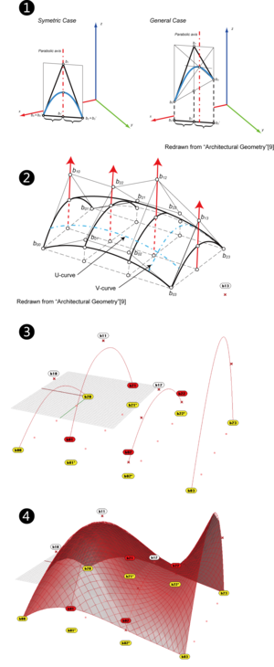
Bezier surface is created from a set of Bezier curves. Several modeling methods of Bezier surfaces exist but "surfaces from parabolas with vertical axes" are used in this research. The method is often used in architectural design because it is simpler than other methods [9].
To create the surface, the control points of a parabolic arc which is a Bezier curve along with parabolic axis on the plan of parabola axis. The 1 of Fig. 2 shows how to do that. In the figure, the 2 cases are shown because the Bezier surfaces consist of 2 kinds of Bezier curves. The symmetric case is used as anchored one to ground so the points b0 and b0’ is same and b1 and b1’ too. The points are defined the size of Bezier curve on XY plan. The General case is different of the symmetric case because the points of b0 and b2 are moveable along with the control points. As shown in the figure, the control point of parabolic arc is b1.
With the parabolic arcs, a Bezier surface is modeled. The 2 of Fig. 2 describes the Bezier surface which is used in the research. The Bezier surfaces have 2 Bezier curves of symmetric case and 2 Bezier curves of general case. The surface is constructed by the grid of top of the surface. To construct a surface, U-curves and V-curves are obtained from the family of the parabolic arcs. The points of b10, b22, b12, and b13, are used as parameters to generate a form for the research.
3.2 Building design system
Recently available systems for generative design are Paracloud by Paracloud, Grasshopper by McNeel, and Generative Components (known as GC) by Bentley. Paracloud and Grasshopper run on Rhino 3D of McNeel as Plug-ins. Generative Components is based on Microstation of Bentley. Paracloud has feature of easy to use but it doesn’t support a function for customizing. Grasshopper has a feature of the graphical algorithm editor and supports the functions for customizing with Microsoft Visual basic script and .Net based. It serves the function which shows explicit logical structure of forms. Generative Components has the strongest function among the systems but it is relatively difficult to use than others. Hence Grasshopper is selected for this research.
To model the surface in CAD, Rhino 3D is used. On the 3 of Fig. 2, 4 Bezier curves are defined on the program. It is consist of 4 parabolic arcs which are 2 symmetric cases used for end of Bezier surface and 2 general cases used for inside the surface. So the points of b00, b20, b03, and b23, define the size of plan for the surface. The 4 of Fig. 2 show the modeled surfaces on the program.
Based on the model, the logic of design forms is developed with using Grasshopper. The logic has 3 core parts which are generating form, creating waffle structure, and creating panel from the surface. Fig. 3 shows the definition of the logic. The waffle structure part is developed by Lift Architects [6], and the surface panelizing part is developed by Designalyze [2].
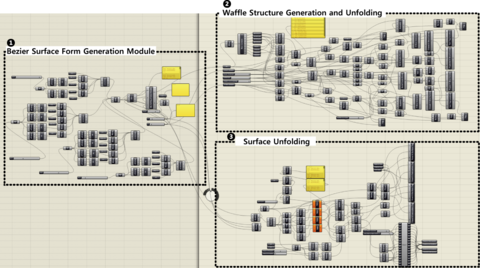
The two employed parts are modified to link with the generating form part so the two parts operate with the form which is generated by the generating part.
A modification is that add the function to collect the coordination of intersection points of U-curves and V-curves and to export the series of the coordination to Micorsoft Excel for fabrication and assemble. However a method of using the Excel data has not been developed yet. Another modification is to connect the surface and the value of number of U-curves and V-curves which are decided in form generation parts.
3.3 Generation and review of the form
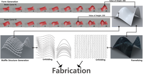
The form generation part generates a form with a changing height of the 4 parabolic arcs which are b10, b11, b12, b13. The heights are controlled by slide components of grasshopper which controls the range of numbers defined by the designer. Form generation in Fig. 4 the upper part of the figure shows the way to generate the form with height values.
The generation of forms is using an animation function of slide component. The animation function creates a series of picture files(saved as BMP file type) with changing the heights which is defined the range of heights by designer. Each pictures shows the identified number and the height on the bottem of the picture. But the hight of four palabolic arcs can’t be changed simultanously so each hight of palabolic arcs must be changed seperatly. At the end of the process, designer can explore design alternatives with the generated pictures and decide an altenetives which is matched his satisfaction. With the heights of the selected pictures. Designer changed the slides of each parbolic arcs by the selected heights and then he can get the final forms like upper right corner form on Fig.4. the process of generation and review can be repeated up to designer find out satisfied form.
3.4 Fabrication
For fabrication, the system uses the waffle structure part and the surface panelizing part. To build up the structure in real world, the form needs a structure to support and panels to cover the structures.
The waffle structure part generates waffle structure depend on definitions of designer which are the number of X-axis and Y-axis structural parts, the thickness of parts, and the size of notches for liking between X-axis and Y-axis structural parts. The method of changing number is same as form generation.
The surface panelizing part is related to the waffle structure part so the number of panels is based on the way of dividing surface by the waffle structure part.
The generating processes in the system can be repeated to satisfy designer with parameters which are heights of parabolic arcs, the number of U-curves and V-curves, the size of parts, and etc. The history of design is showed with the definition of the design logic so designer can change design in any steps of design freely.
To transfer the digital model to fabrication programs which are sort of CAM program, unfold the model on X-Y plan. The two parts can unfold the model with identified number such as X-struct1, A-panel-1 on 3D model and X-Y plan for each part. With the number, designer and fabricator can communicate and recognizes each part.
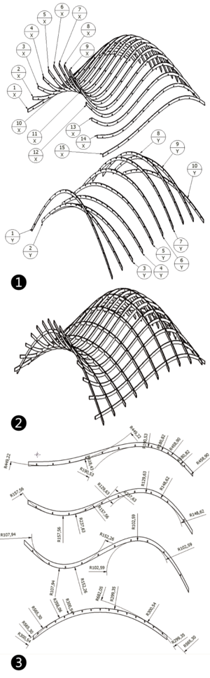
Without using a CAM program, fabrication is possible but it is for a scaled physical model. With using a laser cutter, a cutting plotter, and even cutter, a scaled physical model can be built. But to build the 3D Model in the real world the use of a CAM program is required. In this research, Autodesk Inventor (Inventor) is used and the dwg file format is used to transfer the unfolded drawing. When the unfolded drawing is converted, each part is converted separately, and in Inventor, each component is created as a part. The converted parts are assembled to build up a model with the constraints of the assemble function. The 1 of Fig. 5 shows the exploded drawings in which each part has own tag for recognizing, the 2 of Fig. 5 shows Assembled model by assemble function of Inventor, and the 3 of Fig. 6 shows the radial dimension of selected parts.
However it requires dividing the structural parts because they are so big to handle and to design a method of joint and accessory for joint each structural parts. The panels are converted to inventor.
4. CONCLUSIONS
The design system in the research has done Bezier curve Surface only so through modeling of other type of surface, a possibilities of using variable forms should be served. The method of generation of forms is possible to control each parameter separately. To develop a way to control the parameters simultaneously is required.
The function of unfolding has a limitation which is possible only for shell structures up to now. To cover a tall building, a new unfolding method must be developed.
With inventor, only conversion to the model has been done, but the re-design with structural parts to build based on analysis and design joint accessory.
The form generation requires using the genetic algorithm to support generative design with a variety of design alternatives.
Even if this research has several limitations, the possibilities to adapt the parametric technology for deformed building design and fabrication is recognized through building and testing the design system.
ACKNOWLEDGMENT
This research was supported by the innovation business of the construction technology (No. 06-Advanced Convergence-E01), consigned by Korea Institute of Construction & Transportation technology Evaluation and Planning and funded by Ministry of Land, Transport and Maritime Affairs.
REFERENCES
[1] Carranza P. M., ArchiKlug, armyofclerks.net
[2] designalyze, Surface Penalization Definition, http://www.designalyze.com/, Jan.-16- 2009
[3] Dougherty J., BIM 3.0: Digital Craftsmanship with Revit Architecture and Autodesk Inventor, AB318-4, Autodesk University 2008, DEC.-2008, Las Vegas
[4] Huw W. R. The Importance of Parametrics in Building Information Modeling, AECbytes Viewpoint #5, May 13, 2004
[5] Kolarevic B., Architecture in the Digital Age, Design and Manufacturing, Taylor & Francis, New York, 2003
[6] LIFT Architects, Waffle Structural System: Using Grasshopper to Output Structural Ribs to a Laser Cutter or CNC Mill, http://www.liftarchitects.com/, Oct.-26- 2008
[7] Miller L., Making it Real with Revit and inventor, AB404-2, Autodesk University 2008, DEC.-2008, Las Vegas
[8] Monedero J., Parametric design: A review and some experiences, 15th eCAADe-Conference Proceedings, Vienna University of Technology, September 17-20
[9] Pottman H., Asperl A., Hofer M., Kilian A., Architectural Geometry, Bentley Institute Press, 2007
[10] Schodek D., Bechthold M., Griggs G., et al., Digital Design and Manufacturing – CAD/CAM Application in Arcitecture and Design, Hoboken, New Jersey, 2005
[11] Vollers K., Twist & Build Creating Non-orthogonal architecture, 010 Publishers, Rotterdam, 2001
[12] Widom S., Autodesk Inventor: The Best Tool for Difficult Architectural Details, AB310-5, Autodesk University 2008, DEC.-2008, Las Vegas
No comments:
Post a Comment